
 en
en
 English
 русский
 Español
 عربى
عربى ไทย
ไทยHow an Air Shower Removes Over 95% of Particles?
2026-06-29 - Last Updated: 2026-06-29
Content
- 1 Nozzle Design: Layout, Count, and Angle for Maximum Coverage
- 2 Structural Options: Choosing the Right Air Shower Room Type
- 3 Interlock Control System: Preventing Cross-Contamination
- 4 Filtration System: Pre-Filters and HEPA Filters Working Together
- 5 Air Shower Room Within the Broader Cleanroom System
- 6 Installation Standards and Maintenance Schedule
- 7 Selection Framework: Five Parameters for the Right Decision
- 8 Conclusion
In cleanroom systems, particles carried by personnel and materials are among the largest contamination sources. Air shower rooms use high-speed clean airflow to remove most loose particles attached to human surfaces and material packaging. The clear conclusion: a standard air shower room operating at 25–30 m/s for 15–30 seconds can reduce particles ≥0.5 μm brought in by personnel by more than 95%. This makes it an indispensable pre-treatment device at the entrance of ISO Class 5 to ISO Class 7 cleanrooms, and its performance directly determines the contamination load on the entire clean zone.
Nozzle Design: Layout, Count, and Angle for Maximum Coverage
Nozzle engineering is the most decisive variable in air shower efficiency, directly controlling particle dislodgement rate and coverage blind spots.
Nozzle Layout: Single-sided showers suit low-grade cleanrooms (ISO 7–8). Double-sided is the standard configuration, offering approximately 30% higher efficiency than single-sided. Three-sided showers (both sides plus top) are required for ISO 5–6 high-grade environments to eliminate head and shoulder blind spots.
Nozzle Count: Single-person double-sided air showers typically carry 6–8 nozzles (3–4 per side), ensuring sufficient airflow coverage density across the standing area.
Nozzle Angle: Nozzles should be adjustable within a 0–30° range, aimed at the standing zone. Upper nozzles tilt downward 15–20° for head and shoulder coverage; lower nozzles tilt upward 10–15° for lower leg and foot coverage.
Floor Design: Stainless steel grating or perforated plate with aperture ≤5 mm, with a dust collection drawer underneath for regular cleaning of dislodged particles. Grating load capacity should be ≥300 kg/m² to accommodate material cart passage.
Structural Options: Choosing the Right Air Shower Room Type
The structural configuration of an air shower room should match the facility's throughput requirements and ISO classification. Key types and parameters are outlined below:
| Type | Application | Standard Dimensions | Recommended ISO Class |
|---|---|---|---|
| Single-person, single-sided | Low personnel flow, entry-level cleanrooms | 900 x 1000 x 2100 mm | ISO 7–8 |
| Single-person, double-sided | Standard cleanroom entry | 1000 x 1000 x 2100 mm | ISO 6–7 |
| Single-person, three-sided | Semiconductor, pharmaceutical, high-grade environments | 1200 x 1000 x 2200 mm | ISO 5–6 |
| Walk-through tunnel | High-frequency material and equipment transfer | Custom length 3–6 m | ISO 5–7 |
For high-traffic logistics passages where materials or equipment enter frequently, a walk-through air shower tunnel (custom length 3–6 m) is the recommended solution. Personnel and materials pass through continuously, eliminating repeated door-opening cycles that would disturb cleanroom airflow patterns.
Interlock Control System: Preventing Cross-Contamination
The interlock control system is the logical backbone of contamination prevention in any air shower room installation. A complete interlock architecture includes:
- Dual-door interlock: Entry and exit doors cannot open simultaneously, with interlock response time ≤0.5 seconds. This prevents direct airflow connection between clean and non-clean zones.
- Shower-completion lockout: A timer enforces the full 15–30 second shower cycle before the exit door can open, preventing personnel from bypassing the cleaning process.
- BMS integration: Supports card swipe, fingerprint, or facial recognition (recognition time ≤1 second); links to cleanroom differential pressure sensors with real-time monitoring (range 0–125 Pa, accuracy ≤±1 Pa).
- Alarm functions: Door-open timeout alarms, filter differential pressure overload alarms, with SMS/email/APP push notification support.
Filtration System: Pre-Filters and HEPA Filters Working Together
The air shower filtration system uses two stages to govern supply air cleanliness:
- Pre-filter (G4 grade): Captures larger particles to extend HEPA filter service life. Clean or replace every 3–6 months. In heavy-pollution environments, shorten the cycle accordingly.
- HEPA filter (H13/H14): Achieves ≥99.97% efficiency for particles ≥0.3 μm (H13) or ≥99.99% (H14). Replacement is typically triggered by differential pressure gauge readings, generally every 1–2 years under normal conditions.
The air shower filtration system works in concert with the broader cleanroom filtration infrastructure — including FFU Fan Filter Units, Cleanroom High Efficiency Filters, and FFU Replacement Filters — to establish a controlled particle concentration gradient from the entry point to the core clean zone.
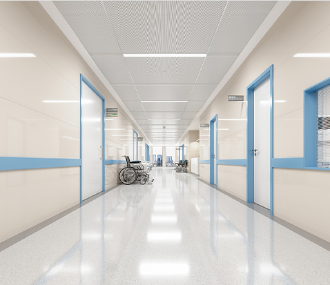
Air Shower Room Within the Broader Cleanroom System
An air shower room functions as the active first line of defense at the entry boundary of a cleanroom system. It operates in coordination with the following components:
- Cleanroom Pass Through Window: Allows materials to transfer between zones without personnel crossing, reducing entry frequency and the associated particle risk.
- FFU Unit (Fan Filter Unit / Modular FFU Unit): Supplies continuous clean air within the cleanroom. EC brushless motor FFUs save more than 50% energy versus traditional AC fan units and support centralized monitoring of up to 8,000 units. Industrial FFU Units and Explosion-proof FFU Fan Filter Units are available for demanding environments.
- Cleanroom Doors and Cleanroom Windows: Qualified cleanroom doors maintain air leakage ≤0.3 m³/(h·m²) at 50 Pa differential pressure. When interlocked with the air shower control system, they prevent pressure gradient disruption across zone boundaries.
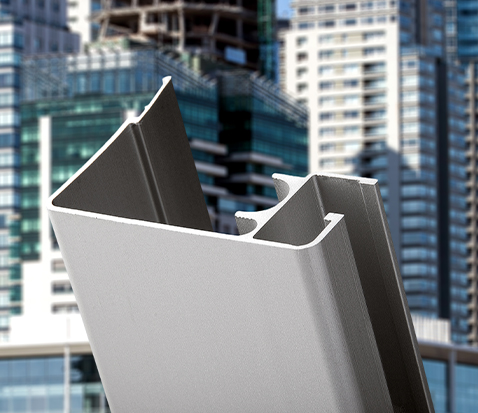
- Cleanroom Wall Panels and Cleanroom Sandwich Panels: The envelope structure surrounding the air shower includes options such as rock wool panels, silicon rock panels, magnesium oxysulfate panels, MGO panels, PU/Polyurethane panels, Stainless Steel Cleanroom Panels, and Aluminum Honeycomb Cleanroom Panels. Modular Cleanroom Panels and Modular Cleanroom Wall Panels enable flexible layout reconfiguration as production needs evolve. Cleanroom Aluminum Profiles form the structural framework connecting all envelope elements.
Installation Standards and Maintenance Schedule
Correct installation and disciplined maintenance are prerequisites for sustained air shower performance. The table below summarizes the key requirements:
| Item | Standard Requirement | Frequency |
|---|---|---|
| Chamber-to-wall gap | ≤2 mm, filled with neutral sealant | At installation |
| Floor levelness | Deviation ≤2 mm/m | At installation |
| Power cable specification | Flame-retardant 3×1.5 mm², dedicated circuit | At installation |
| Interior walls, grating, dust drawer cleaning | Wipe stainless steel walls daily; clean drawer weekly | Daily / Weekly |
| Fan inlet inspection | Remove accumulated dust | Monthly |
| Pre-filter (G4) | Clean or replace | Every 3–6 months |
| HEPA filter (H13/H14) | Replace based on differential pressure gauge reading | Every 1–2 years |
| Nozzle exit velocity test | If below 20 m/s, check fan or filter for issues | Every 6 months |
Selection Framework: Five Parameters for the Right Decision
Use the following five-dimensional framework to avoid under-specification or over-investment when selecting an air shower room:
- ISO classification: ISO 7 and above should use double-sided or three-sided configurations. ISO 5–6 requires three-sided shower with H14 HEPA filtration as a minimum.
- Personnel throughput: Single-person chambers suit ≤20 personnel passes per hour. High-traffic facilities should use double-person chambers or walk-through tunnels to eliminate queuing-induced secondary contamination.
- Material and cart dimensions: Confirm grating load capacity ≥300 kg/m² and chamber width sufficient for the largest material cart. Tunnel configurations are strongly recommended for regular cart traffic.
- Material specification: Pharmaceutical Cleanroom Systems and Medical Cleanroom Panels applications require stainless steel interior walls (304 or 316L) to meet GMP no-dead-corner cleaning requirements. Laboratory Cleanroom Panels environments may use powder-coated cold-rolled steel based on budget constraints.
- Integration interface: Confirm the communication protocol for BMS integration (MODBUS RTU or dry contact), and the interlocking requirements with FFU systems and differential pressure monitoring infrastructure.
Conclusion
An air shower room is not a supplementary accessory in a cleanroom system — it is the primary active contamination barrier at the human-cleanroom boundary. It must be designed and selected as part of the overall Clean Room Systems framework, working in concert with Cleanroom Wall Panels, FFU Units, Cleanroom Pass Through Windows, and Cleanroom Doors and Windows to form a complete contamination control chain. When nozzle geometry, structural parameters, interlock logic, and maintenance protocols are correctly executed, an air shower room reliably delivers over 95% particle removal efficiency over its full service life, protecting both ISO classification compliance and product quality outcomes.
Message Feedback
Product Categories
Easily navigate and discover our complete range of solutions through our logically structured product
categories.


- E-Mail: [email protected]
- Tel: +86 18968239620
- Address: Room No.905, He Yuan Mansion, No. 382, Tianda Lane, Ningbo Southern Business District, Yinzhou Ningbo China
Quick Links
Contact Us
© Copyright Zhejiang Kaisier Clean Technology Co.,Ltd.
All Rights Reserved.
 Cleanroom Systems Manufacturer
Modular Cleanroom Solutions Factory
Cleanroom Systems Manufacturer
Modular Cleanroom Solutions Factory
-
+86 18968239620
-
-
