
 en
en
 English
 русский
 Español
 عربى
عربى ไทย
ไทย


-
Kaisier Clean Technology Announces Official Operation of New Thailand Production Base, Enhancing Global Supply Chain Resilience
Jan, 30, 2026
Industry NewsZhejiang Kaisier Clean Technology Co., Ltd., a leading provider of high-performance cleanroom solutions, is proud to announce the official commencement of operations at its state-of-the-art production base in Thailand, u... -
Kaiser Unveils Next-Gen Antimicrobial Clean Panel Series, Setting New Benchmark for Healthcare & High-Tech Facilities
Jan, 30, 2026
Industry NewsInnovating at the intersection of safety and purity, Zhejiang Kaiser Clean Technology Co., Ltd. has launched its next-generation clean panel series, engineered with proprietary advanced surface treatment technology. This... -
Kaisier Clean Technology Showcases Total Cleanroom Solutions at SEMICON Southeast Asia 2024, Highlighting “One-Stop Service” Model
Jan, 30, 2026
Industry NewsZhejiang Kaisier Clean Technology Co., Ltd., together with its Thai subsidiary, successfully participated as an exhibitor at SEMICON Southeast Asia 2024, one of the region’s premier events for the microelectronics manufa...
C-shaped steel purlins Manufacturer
C-shaped steel purlins are thin-walled steel structural components with C-shaped cross-sections formed by cold bending. They are mainly used for load support and force transmission systems in the roofs and walls of steel structure buildings. C-shaped steel purlins possess core characteristics such as stable cross-sectional mechanical properties, light weight, high strength-to-weight ratio, reliable corrosion resistance, and strong installation adaptability. They can evenly bear the load of the cladding panels and transfer it to the main structure, making them suitable for industrial plants, warehouses, logistics centers, stadiums, and photovoltaic support systems.
Product Categories
About Kaisier
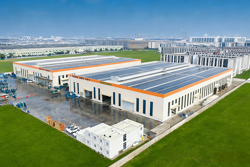
Kaisier Cleans the Globe Tech Empowers Tomorrow
Zhejiang Kaisier Clean Technology Co.,Ltd. upholding the brand mission of "Kaisier Cleans the Globe, Tech Empowers Tomorrow", Zhejiang Kaisier Clean Technology Co., Ltd. and its Thai subsidiary are a technology-driven enterprise in the clean industry with a global layout. The company has built four modern production bases in China and Thailand, forming a "domestic coordination + international radiation" capacity network equipped with intelligent production lines and precision testing equipment to ensure stable and efficient supply.
We are a China OEM/ODM C-shaped steel purlins Company and C-shaped steel purlins Manufacturer, specialize in R&D, production and sales of a full range of clean panels, including color steel sandwich panels, rock wool clean panels and magnesium oxide clean panels, which can meet the stringent requirements of Class 100 to Class 300,000 air purification projects. Our products lead the world in fire resistance, antibacterial and antistatic performance, and are widely applied in high-end fields such as healthcare, electronics and food industries, providing one-stop services from solution design to after-sales support. With technological innovation as the core and the philosophy of "precision engineering for ultimate cleanliness", we are committed to delivering safe and reliable clean space solutions for global customers.
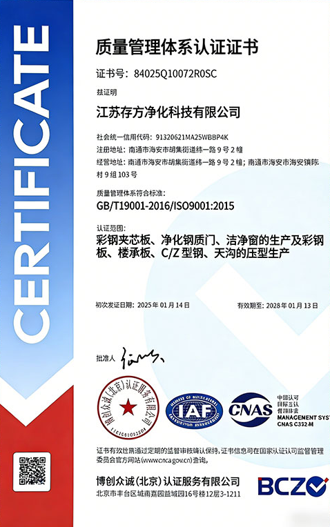
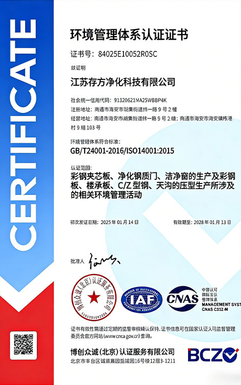
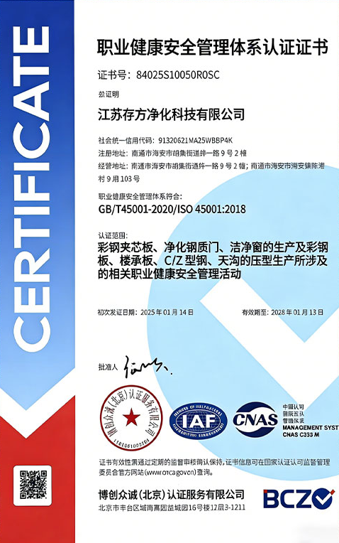
Certificate Of Honor
Our Latest News
Message Feedback
C-shaped steel purlins Industry knowledge
C-shaped steel purlins are thin-walled, cold-formed structural members with a C-shaped cross-section that serve as the critical load-transfer link between roof or wall cladding panels and the primary steel frame. Their defining advantages—stable cross-sectional mechanical properties, high strength-to-weight ratio, and straightforward installation—make them the preferred choice for industrial plants, warehouses, logistics centers, and light commercial buildings with spans up to 25 feet (7.6 meters) [^103^]. Unlike Z-purlins, which require overlapping for continuous spans, C-purlins excel in single-span and simple-span applications where speed of erection and cost efficiency are paramount.
For projects requiring wall support, floor joists, or single-bay roofing, C-purlins offer a 20–30% cost savings over Z-purlin systems while eliminating the complexity of lap connections. Their 90-degree flange geometry ensures predictable load paths and simplifies bracket detailing, making them the go-to solution for pre-engineered metal buildings and steel structure frameworks worldwide.
Cross-Sectional Geometry and Structural Behavior
The C-shaped profile is mono-symmetrical, featuring a vertical web with two parallel horizontal flanges oriented at 90 degrees to the web. This geometry delivers predictable mechanical behavior under gravity and wind loads.
Section Properties and Load Distribution
The C-section provides stable flexural performance about its strong axis (perpendicular to the web), making it ideal for supporting uniformly distributed roof and wall loads. The parallel flanges create consistent bearing surfaces for cladding fasteners and bracket connections. However, because the section is open and mono-symmetrical, it exhibits lower torsional rigidity than closed or Z-shaped sections. This characteristic makes C-purlins best suited for applications where loads are applied through the shear center or where bridging is provided to restrain lateral-torsional buckling [^95^].
Span Capabilities by Section Depth
Standard C-purlin depths range from 100 mm to 400 mm (4 in to 16 in), with each depth corresponding to specific span and load limits. The following table summarizes typical spanning capabilities under standard roof loads [^103^]:
| Section Depth | Metric Depth | Maximum Single Span | Typical Application |
|---|---|---|---|
| C4 | 100 mm | Up to 12 ft (3.7 m) | Light residential, small sheds |
| C6 | 150 mm | Up to 18 ft (5.5 m) | Standard residential, light commercial |
| C8 | 200 mm | Up to 25 ft (7.6 m) | Medium commercial, small warehouses |
| C10 | 250 mm | Up to 30 ft (9.1 m) | Heavy-duty commercial, mid-size industrial |
| C12 | 300 mm | Up to 35+ ft (10.7+ m) | Large industrial, heavy-load applications |
Actual spanning capability depends on purlin spacing, steel thickness (gauge), roof load (dead + live + snow), and local building code requirements. For spans exceeding 8 meters, Z-purlins with lapped connections typically become more economical than single C-purlin sections [^102^].
Material Specifications and Manufacturing Standards
The durability and structural integrity of C-purlins are governed by base steel grade, coating systems, and cold-forming precision.
Base Steel and Mechanical Properties
C-purlins are manufactured from cold-formed galvanized steel strip with a minimum yield strength of 345 N/mm² (50 ksi), equivalent to ASTM A572 Grade 50 or AS/NZS 1397 G450 material. Standard base metal thicknesses (BMT) range from 1.5 mm to 3.0 mm (0.059 in to 0.118 in), with heavier gauges selected for higher load or wider spacing applications [^97^]. The cold-forming process work-hardens the steel, increasing its yield strength by 10–15% compared to the parent coil material.
Corrosion Protection Systems
Three coating options dominate the market:
- Hot-dip galvanized (Zinc coating): Standard coating mass of 180–275 g/m² (Z180–Z275), providing 40+ years of corrosion resistance in benign indoor environments [^96^].
- ZAM coating (Zinc-Aluminum-Magnesium): Advanced alloy coating offering 2–3× the corrosion resistance of pure zinc, ideal for coastal or high-humidity industrial settings [^104^].
- Prime-painted finish: Applied over galvanized substrate for aesthetic consistency with colored cladding panels; not a standalone corrosion barrier.
Manufacturing Tolerances
Precision manufacturing ensures fit-up quality during installation. Standard production tolerances are [^101^]:
- Length: ±5 mm
- Flange width: ±1 mm
- Web depth: ±1 mm
- Hole center spacing: ±1.5 mm
C-Purlin vs. Z-Purlin: Selection Criteria
While both C and Z sections serve as secondary framing members, their distinct geometries create meaningful performance differences that dictate application suitability.
| Feature | C-Purlin | Z-Purlin |
|---|---|---|
| Cross-sectional shape | C-shape, 90° flanges | Z-shape, angled flanges |
| Connection method | End-to-end, bracketed | Lapped overlap at supports |
| Span capability | Short to medium (≤25 ft) | Long spans (up to 60+ ft) |
| Load capacity | Light to moderate loads | Higher load capacity |
| Roof slope adaptability | Limited, best for flat/low slope | Superior for pitched roofs |
| Installation complexity | Simple, fast, minimal drilling | Requires lap alignment skill |
| Cost efficiency | Lower material + labor cost | Higher initial cost, better for large spans |
The fundamental rule of thumb: use C-purlins for wall girts, floor joists, and single-span roofs under 8 meters; specify Z-purlins for multi-span roofs, large industrial bays, and projects with heavy snow or wind loads [^96^].
Installation Best Practices and Bracing Requirements
Proper installation transforms C-purlins from individual members into a coherent structural system capable of resisting gravity, wind, and seismic loads.
Purlin Spacing and Support Details
Standard purlin spacing for metal roofing ranges from 1.2 m to 1.8 m (4 ft to 6 ft) on center, depending on cladding profile and design loads. C-purlins are supported by angle connector brackets or general-purpose brackets bolted to the primary frame rafters or columns. Bracket selection must match the purlin depth: a C150 purlin requires an AC150 bracket (0.30 kg each), while a C300 purlin requires an AC300 bracket (0.69 kg each) [^101^].
Bridging for Lateral Stability
Because open C-sections are susceptible to lateral-torsional buckling, bridging (also called sag rods or fly bracing) is essential. Bridging limits the unbraced length of the compression flange and prevents rotation under load. Recommended maximum bridging spacing is:
- C100 sections: 2000 mm maximum spacing
- C150 sections: 3000 mm maximum spacing
- C200–C400 sections: 4000 mm maximum spacing [^101^]
Bridging is typically installed at mid-span for single spans and at third-points for continuous spans. HookFast-style bridging systems allow tool-free installation by clipping directly to prepunched holes in the purlin web.
Installation Sequence
The recommended erection sequence ensures both safety and dimensional accuracy:
- Mark purlin lines on the primary frame members at the specified spacing.
- Install brackets at each purlin support point, ensuring level alignment within ±3 mm.
- Place C-purlins onto brackets with the open side oriented consistently (typically downward for roof purlins to facilitate bridging attachment).
- Bolt purlins to brackets using M12 or M16 bolts with washers; torque to 50–70 N·m.
- Install bridging before applying roof or wall cladding to stabilize the purlin line.
- Verify alignment: purlin tops should be level within L/360 deflection limit under dead load.
Applications Across Industry Sectors
C-shaped steel purlins are deployed across a broad spectrum of construction types, each imposing distinct performance demands.
Industrial Plants and Warehouses
In pre-engineered steel buildings for manufacturing and storage, C-purlins support trapezoidal roof sheets and wall cladding panels. Typical bay widths of 6–8 meters align perfectly with C200 or C250 purlin capacities. The lightweight nature of C-purlins (C200×1.5 mm weighs approximately 4.5 kg/m) reduces crane demands during erection and lowers the overall dead load on the primary frame [^101^].
Logistics Centers and Distribution Hubs
Modern logistics facilities require wide clear spans and high eave heights. While primary frames often use Z-purlins for the main roof, C-purlins are frequently specified for mezzanine floors, canopies, and partition walls where spans are shorter and loads are lighter. Their ease of installation accelerates project delivery in fast-track developments.
Photovoltaic Support Systems
C-purlins have emerged as a preferred framing element for ground-mounted solar arrays and rooftop PV installations. Their open channel profile readily accepts bolted clamp connections for solar panel rails, and the galvanized coating withstands decades of outdoor exposure. Standard C150 or C200 sections at 1.5–2.0 m spacing provide adequate support for typical PV module dimensions of 1.0 m × 2.0 m.
Agricultural and Rural Buildings
Farm buildings, equipment sheds, and livestock shelters benefit from C-purlins' cost efficiency and corrosion resistance. In these applications, C100 or C150 sections at moderate spans provide sufficient capacity for metal roofing while keeping material costs minimal. The 40+ year service life of galvanized C-purlins delivers long-term value in rural settings where maintenance access may be limited [^96^].
Quality Control and Compliance Standards
Ensuring C-purlin performance requires adherence to recognized material and design standards throughout the supply chain.
Material and Design Codes
C-purlin design and manufacturing are governed by the following standards:
- AS/NZS 4600:2018 (Australia/New Zealand): Cold-formed steel structures design code, widely referenced for purlin capacity calculations.
- ASTM A1003/A1004 (USA): Standard specification for steel sheet used in cold-formed framing.
- EN 1993-1-3 (Europe): Eurocode 3 design rules for cold-formed thin-gauge members and sheeting.
- GB/T 2518 (China): Standard for continuously hot-dip zinc-coated steel sheets and strips.
Factory Quality Assurance
Reputable manufacturers implement ISO 9001 quality management systems with the following inspection protocols:
- Incoming coil inspection: Verify yield strength, coating mass, and thickness tolerance against mill certificates.
- In-process monitoring: Check roll-forming dimensions every 2 hours; adjust roller gaps to maintain profile accuracy.
- Hole punching verification: Confirm hole centers, diameters, and edge distances using go/no-go gauges.
- Final inspection: Measure length, straightness, and surface finish on every bundle; reject pieces with coating damage or dimensional non-conformance.
- E-Mail: [email protected]
- Tel: +86 18968239620
- Address: Room No.905, He Yuan Mansion, No. 382, Tianda Lane, Ningbo Southern Business District, Yinzhou Ningbo China
Quick Links
Contact Us
© Copyright Zhejiang Kaisier Clean Technology Co.,Ltd.
All Rights Reserved.
 OEM/ODM C-shaped steel purlins Company
C-shaped steel purlins Manufacturer
OEM/ODM C-shaped steel purlins Company
C-shaped steel purlins Manufacturer
-
+86 18968239620
-
-
