
 en
en
 English
 русский
 Español
 عربى
عربى ไทย
ไทย


-
Kaisier Clean Technology Announces Official Operation of New Thailand Production Base, Enhancing Global Supply Chain Resilience
Jan, 30, 2026
Industry NewsZhejiang Kaisier Clean Technology Co., Ltd., a leading provider of high-performance cleanroom solutions, is proud to announce the official commencement of operations at its state-of-the-art production base in Thailand, u... -
Kaiser Unveils Next-Gen Antimicrobial Clean Panel Series, Setting New Benchmark for Healthcare & High-Tech Facilities
Jan, 30, 2026
Industry NewsInnovating at the intersection of safety and purity, Zhejiang Kaiser Clean Technology Co., Ltd. has launched its next-generation clean panel series, engineered with proprietary advanced surface treatment technology. This... -
Kaisier Clean Technology Showcases Total Cleanroom Solutions at SEMICON Southeast Asia 2024, Highlighting “One-Stop Service” Model
Jan, 30, 2026
Industry NewsZhejiang Kaisier Clean Technology Co., Ltd., together with its Thai subsidiary, successfully participated as an exhibitor at SEMICON Southeast Asia 2024, one of the region’s premier events for the microelectronics manufa...
Air Shower Room Manufacturer
An air shower (also known as an air shower room, air shower booth, air shower door, air blowing room, AIR SHOWER, air shower equipment, or air shower machine) is a versatile local purification device installed in the partition wall between clean and non-clean rooms. It is used to remove dust from personnel or objects before they enter the clean area. Its use effectively reduces the entry of dust sources into the clean area, maintaining the clean area in a normal working state. It is widely used in various industries such as food and beverage, electronics, pharmaceuticals, and healthcare, as well as in scientific research fields.
Product Categories
About Kaisier
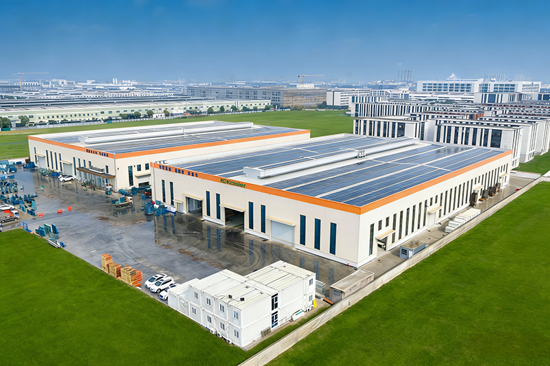
Kaisier Cleans the Globe Tech Empowers Tomorrow
Zhejiang Kaisier Clean Technology Co.,Ltd. upholding the brand mission of "Kaisier Cleans the Globe, Tech Empowers Tomorrow", Zhejiang Kaisier Clean Technology Co., Ltd. and its Thai subsidiary are a technology-driven enterprise in the clean industry with a global layout. The company has built four modern production bases in China and Thailand, forming a "domestic coordination + international radiation" capacity network equipped with intelligent production lines and precision testing equipment to ensure stable and efficient supply.
We are a China OEM/ODM Air Shower Company and Air Shower Room Manufacturer, specialize in R&D, production and sales of a full range of clean panels, including color steel sandwich panels, rock wool clean panels and magnesium oxide clean panels, which can meet the stringent requirements of Class 100 to Class 300,000 air purification projects. Our products lead the world in fire resistance, antibacterial and antistatic performance, and are widely applied in high-end fields such as healthcare, electronics and food industries, providing one-stop services from solution design to after-sales support. With technological innovation as the core and the philosophy of "precision engineering for ultimate cleanliness", we are committed to delivering safe and reliable clean space solutions for global customers.
Certificate Of Honor
Our Latest News
Message Feedback
Air shower Industry knowledge
In cleanroom systems, particles carried by personnel and materials are among the largest sources of contamination. Air shower rooms use high-speed clean airflow to remove most loose particles attached to human surfaces and material packaging. The clear conclusion is: A standard air shower operating at 25-30 m/s for 15-30 seconds can reduce particles ≥0.5μm brought in by personnel by more than 95%, making it an indispensable pre-treatment device at the entrance of ISO Class 5 to ISO Class 7 cleanrooms. Its performance directly determines the contamination load on the clean zone. The following provides in-depth technical reference from five dimensions: air shower efficiency, structural parameters, nozzle design, interlock control, and selection要点.
Air Shower Efficiency: Key Performance Indicators and Data
The core performance of an air shower is particle removal efficiency. Industry-recognized key indicators are as follows:
| Performance Parameter | Industry Benchmark | High-Quality Unit Typical Value | Significance for Cleanroom |
|---|---|---|---|
| Particle Removal Efficiency (≥0.5μm) | ≥90% (30 sec cycle) | ≥98% (30 sec cycle) | Reduces clean zone contamination load by 80%-95% |
| Nozzle Exit Velocity (m/s) | ≥20 m/s | 25-30 m/s | Higher velocity provides better dust removal |
| Nozzle Velocity Uniformity | ≤±20% | ≤±15% | Eliminates dead zones in air shower |
| HEPA/ULPA Filter Efficiency | H13 (99.97% @0.3μm) | H14 (99.995%) or U15 | Ensures cleanliness of the shower air |
| Personnel Surface Particle Residue (≥0.5μm) | ≤500 particles/m² | ≤200 particles/m² | Required for high-grade cleanrooms |
Structural Design: Dimensions, Materials, and Nozzle Layout
The structural design of an air shower directly affects user experience and shower effectiveness. Key design parameters are as follows:
- Overall dimensions: Standard single-person air shower dimensions (W×D×H) are 1200×1000×2100mm, with passage dimensions 800×900×1950mm. Double-person air showers have width 1500-1800mm. For material air showers, depth should be increased to 1500-2000mm;
- Chamber material: Exterior walls use 1.2-1.5mm cold-rolled steel with electrostatic spray coating; interior walls use 1.0-1.2mm stainless steel (304). The ceiling and floor also use stainless steel, with the floor requiring anti-slip embossing (pattern height 0.3-0.5mm);
- Nozzle layout: Single-sided shower is suitable for low-grade cleanrooms (ISO 7-8); double-sided shower is standard, offering about 30% higher efficiency than single-sided; three-sided shower (both sides + top) is suitable for ISO 5-6 high-grade cleanrooms, covering head and shoulder blind spots. Nozzle count: single-person double-sided air showers typically have 6-8 nozzles (3-4 per side);
- Nozzle angle: Nozzles should be adjustable (0-30°), aimed at the standing area. Upper nozzles tilt downward 15-20° for head and shoulder coverage; lower nozzles tilt upward 10-15° for lower leg and foot coverage;
- Floor design: Stainless steel grating or perforated plate with aperture ≤5mm, with a dust collection drawer underneath for regular cleaning of dislodged particles. Grating load capacity should be ≥300 kg/m² to accommodate cart passage.
For high-traffic logistics passages (e.g., materials, equipment entry), a walk-through air shower tunnel (custom length 3-6 meters) is recommended, where personnel complete the shower while walking through, offering higher efficiency and avoiding congestion.
Fan and Filtration System: The Core of Airflow Power and Cleanliness
The fan and filter of an air shower determine shower velocity and air cleanliness. A quantitative comparison is shown below:
| Configuration Level | Fan Type | Filter Grade | Exit Velocity (m/s) | Applicable Cleanliness Class |
|---|---|---|---|---|
| Economy | Forward curved centrifugal, single speed | H13 (99.97%) | 20-22 | ISO 7-8 (Class 10,000+) |
| Standard | Backward curved centrifugal, dual-speed adjustable | H14 (99.995%) | 25-28 | ISO 6-7 (Class 1,000-10,000) |
| High-Grade | EC fan, infinitely variable speed + VFD | U15 (99.9995%) | 28-32 | ISO 5-6 (Class 100-1,000) |
Interlock Control and Access Control System
The door control logic of an air shower is a core mechanism for preventing cross-contamination. A complete control system should meet the following requirements:
- Electronic interlock: The entry and exit doors cannot be opened simultaneously. When one door opens, the other is automatically locked; both doors are locked during the air shower cycle;
- Air shower logic: Personnel enter → entry door closes → sensor detects personnel (infrared or micro switch) → fan automatically starts → shower timer begins (adjustable 15-99 seconds) → after shower ends, 1-2 second delay → exit door unlocks;
- Emergency function: In case of power failure or emergency, both doors must be manually openable with opening force ≤67N to meet egress requirements. An emergency stop button should also be provided — when pressed, the fan stops immediately and both doors unlock;
- Access control integration (optional): Can be integrated with IC card, fingerprint, or facial recognition systems, allowing only authorized personnel to unlock the entry door. The controller should record each shower's time, personnel information, and equipment status;
- Voice guidance: High-quality air showers should be equipped with a voice guidance system to guide personnel through the shower process (e.g., "Please enter the air shower", "Please raise your arms and turn around", "Shower in progress, do not open the door", etc.).
Interlock system reliability requirements: MTBF ≥50,000 hours, interlock response time ≤0.5 seconds. Interlock function testing is recommended monthly to ensure safety and reliability.
Installation and Maintenance: Key On-Site Points
Proper installation and regular maintenance of air showers are critical for ensuring long-term performance. Key points are as follows:
- On-site installation: The air shower should be installed at the cleanroom entry partition, with gap between chamber and wall panel ≤2mm, filled with neutral sealant. The floor should be level with the ground, levelness deviation ≤2mm/m. Power cables should use flame-retardant cables of at least 3×1.5mm², with a dedicated circuit;
- Filter replacement cycle: Pre-filters (G4 grade) should be cleaned or replaced every 3-6 months; HEPA filters (H13/H14) are generally replaced every 1-2 years based on differential pressure gauge readings. In dusty or heavily polluted environments, replacement cycles should be shortened;
- Daily cleaning: Clean stainless steel interior walls, floor grating, and dust collection drawer daily. The dust collection drawer is recommended for weekly cleaning to avoid particle re-entrainment. Fan inlets should be inspected monthly to remove accumulated dust;
- Velocity and filter leak testing: Measure nozzle exit velocity every six months; if below 20 m/s, check for fan or filter blockage. Perform PAO leak testing annually to ensure HEPA filters are leak-free;
- Common troubleshooting: Fan not running → check power, fuse, overload protection; insufficient velocity → check filter blockage, fan rotation direction; door lock failure → check solenoid coil, magnetic door switch, and control board.
Establishing a quarterly maintenance log recording filter differential pressure, velocity, noise levels, and repair history is a best practice for ensuring long-term stable operation of air showers.
Selection Recommendations: Choosing Air Showers by Cleanliness Class and Application Scenario
The following are selection recommendations for four typical application scenarios:
| Application Scenario | Recommended Type | Recommended Velocity (m/s) | Shower Time (seconds) | Special Requirements |
|---|---|---|---|---|
| Electronics/Semiconductor ISO 5-6 | Three-sided + EC fan | 28-32 | 20-30 | ULPA filter (U15), stainless steel interior |
| Pharmaceutical GMP ISO 7 | Double-sided + H14 | 25-28 | 15-20 | VHP disinfectant-resistant materials, voice guidance |
| Food/Health Products ISO 7-8 | Double-sided + H13 | 22-25 | 15-20 | 304 stainless steel, easy-clean design |
| Logistics/Material Passage | Walk-through tunnel (3-6m) | 20-25 | Shower while walking | Reinforced floor load capacity, CIP optional |
- E-Mail: [email protected]
- Tel: +86 18968239620
- Address: Room No.905, He Yuan Mansion, No. 382, Tianda Lane, Ningbo Southern Business District, Yinzhou Ningbo China
Quick Links
Contact Us
© Copyright Zhejiang Kaisier Clean Technology Co.,Ltd.
All Rights Reserved.
 OEM/ODM Air Shower Company
Air Shower Room Manufacturer
OEM/ODM Air Shower Company
Air Shower Room Manufacturer
-
+86 18968239620
-
-
