
 en
en
 English
 русский
 Español
 عربى
عربى ไทย
ไทย


-
Kaisier Clean Technology Announces Official Operation of New Thailand Production Base, Enhancing Global Supply Chain Resilience
Jan, 30, 2026
Industry NewsZhejiang Kaisier Clean Technology Co., Ltd., a leading provider of high-performance cleanroom solutions, is proud to announce the official commencement of operations at its state-of-the-art production base in Thailand, u... -
Kaiser Unveils Next-Gen Antimicrobial Clean Panel Series, Setting New Benchmark for Healthcare & High-Tech Facilities
Jan, 30, 2026
Industry NewsInnovating at the intersection of safety and purity, Zhejiang Kaiser Clean Technology Co., Ltd. has launched its next-generation clean panel series, engineered with proprietary advanced surface treatment technology. This... -
Kaisier Clean Technology Showcases Total Cleanroom Solutions at SEMICON Southeast Asia 2024, Highlighting “One-Stop Service” Model
Jan, 30, 2026
Industry NewsZhejiang Kaisier Clean Technology Co., Ltd., together with its Thai subsidiary, successfully participated as an exhibitor at SEMICON Southeast Asia 2024, one of the region’s premier events for the microelectronics manufa...
FFU Unit Manufacturer
Product Features:
The fan uses a German EBM direct-drive high-efficiency centrifugal fan, which features a long lifespan, low noise, maintenance-free operation, low vibration, and stepless speed control. The fan is reliable and has a working life of over 50,000 hours.
It is particularly suitable for modular ultra-clean production lines and can be used individually or connected in series to form a Class 100 assembly line, depending on process requirements.
The housing is made of stainless steel, aluminum alloy, or cold-rolled steel plate, resulting in a lightweight, corrosion-resistant, rust-proof, and aesthetically pleasing design.
Before leaving the factory, each product is individually scanned and tested using a particle counter according to US Federal Standard 209E to ensure quality.
Optional accessories:
German EBM DC fan, featuring energy saving, centralized computer control, stable operation, low noise, and digital speed control. It can save more than 50% energy under the initial resistance of the high-efficiency filter, resulting in low operating costs. One computer can centrally control the operation, speed adjustment, and status monitoring of nearly 8000 fans.
ULPA ultra-high efficiency filter.
Circular duct interface.
Product Categories
About Kaisier
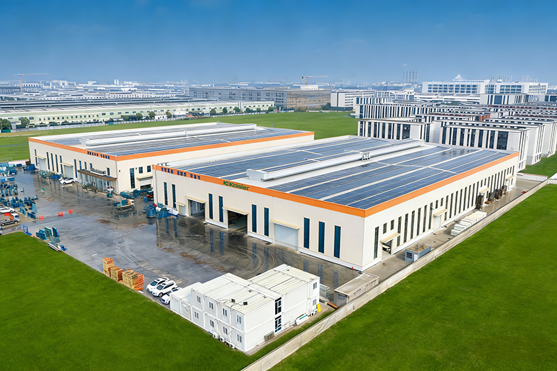
Kaisier Cleans the Globe Tech Empowers Tomorrow
Zhejiang Kaisier Clean Technology Co.,Ltd. upholding the brand mission of "Kaisier Cleans the Globe, Tech Empowers Tomorrow", Zhejiang Kaisier Clean Technology Co., Ltd. and its Thai subsidiary are a technology-driven enterprise in the clean industry with a global layout. The company has built four modern production bases in China and Thailand, forming a "domestic coordination + international radiation" capacity network equipped with intelligent production lines and precision testing equipment to ensure stable and efficient supply.
We are a China OEM/ODM Fan Filter Unit Company and FFU Unit Manufacturer, specialize in R&D, production and sales of a full range of clean panels, including color steel sandwich panels, rock wool clean panels and magnesium oxide clean panels, which can meet the stringent requirements of Class 100 to Class 300,000 air purification projects. Our products lead the world in fire resistance, antibacterial and antistatic performance, and are widely applied in high-end fields such as healthcare, electronics and food industries, providing one-stop services from solution design to after-sales support. With technological innovation as the core and the philosophy of "precision engineering for ultimate cleanliness", we are committed to delivering safe and reliable clean space solutions for global customers.
Certificate Of Honor
Our Latest News
Message Feedback
FFU unit Industry knowledge
In cleanroom systems, the FFU (Fan Filter Unit) is the core device that supplies clean air, integrating a fan and high-efficiency filter and mounting directly onto the ceiling grid. The clear conclusion is: The energy efficiency, noise level, service life, and control method of an FFU directly determine the operating cost and cleanliness stability of a cleanroom. An FFU equipped with an EC brushless DC fan and H14 high-efficiency filter can reduce energy consumption by more than 50% compared to traditional AC fan units at rated airflow, maintain noise levels within 52dB, and offer centralized monitoring and group control capabilities. The following provides in-depth technical reference from five dimensions: fan type, filtration system, housing construction, intelligent control, and selection parameters.
Fan Types: Comprehensive Comparison of EC vs. AC Fans
The fan is the core component of an FFU, directly determining energy consumption, noise level, and service life. A detailed comparison of the two mainstream fan types is shown below:
| Performance Parameter | EC Brushless DC Fan | AC Fan (Traditional) | Advantage Comparison |
|---|---|---|---|
| Motor Efficiency (%) | ≥70% | 40-50% | EC reduces energy consumption by 40%+ |
| Speed Control Method | 0-10V/PWM/RS485 stepless | Transformer/triac (stepped or limited) | EC offers smoother, wider control range |
| Noise Level (dBA) | 48-52 @ rated airflow | 55-62 @ rated airflow | EC is 3-10dB quieter |
| Design Life (hours) | ≥80,000 (e.g., German EBM) | 50,000-60,000 | EC lifespan 30-60% longer |
| Maintenance Requirements | Maintenance-free (brushless) | Carbon brush/capacitor replacement | EC is maintenance-free |
| Relative Cost | Baseline +30-50% | Baseline | EC payback period approx. 1-2 years |
Filtration System: HEPA vs. ULPA Selection and Leak Testing
The filter of an FFU determines the cleanliness level of the supplied air. Technical parameters and application scenarios for different filter grades are shown below:
| Filter Grade | Efficiency (@0.3μm) | Initial Resistance (Pa) | Applicable Cleanliness Class | Typical Applications |
|---|---|---|---|---|
| H13 (HEPA) | 99.97% | 180-220 | ISO 7-8 (Class 10,000/100,000) | Electronics assembly, food packaging |
| H14 (HEPA) | 99.995% | 220-280 | ISO 6 (Class 1,000) | Pharmaceutical GMP, medical devices |
| U15 (ULPA) | 99.9995% | 250-320 | ISO 5 (Class 100) | Semiconductor lithography, BSL labs |
| U17 (ULPA) | 99.999995% | 300-380 | ISO 4-5 (Class 10/100) | Advanced semiconductor, nanotechnology |
Housing Construction and Materials: Balancing Lightweight and Corrosion Resistance
Three materials are commonly used for FFU housings: stainless steel, aluminum alloy, and cold-rolled steel. A detailed comparison is shown below:
| Material | Weight (kg/unit) | Corrosion Resistance | Surface Finish | Applicable Scenarios | Relative Cost |
|---|---|---|---|---|---|
| 304 Stainless Steel | 25-30 | Excellent | Brushed/Mirror | Pharmaceutical, food, corrosive environments | Baseline +50% |
| Aluminum Alloy | 18-22 | Good | Anodized | Electronics cleanrooms, lightweight applications | Baseline +20% |
| Cold-Rolled Steel + Powder Coating | 20-25 | Fair | Electrostatic spray (≥80μm) | General industry, low-budget projects | Baseline |
Intelligent Control Systems: Group Control and Energy Monitoring
In modern cleanrooms, FFUs are often numerous (hundreds to thousands of units), requiring intelligent control systems for centralized management. The core functions of the control system are as follows:
- Centralized monitoring platform: A single computer can centrally control up to 8,000 EC fan FFUs, monitoring each fan's speed, operating status, fault alarms, and cumulative runtime in real time;
- Zone grouping control: FFUs can be grouped by area or cleanliness class for unified speed adjustment and start/stop control. For example, high-speed operation during production hours, automatic switch to low-speed energy-saving mode at night or during non-production hours;
- Differential pressure interlocking: Linked to cleanroom differential pressure sensors, automatically increasing FFU speed when room pressure drops below setpoint to maintain pressure stability;
- Energy consumption statistics and optimization: The system automatically calculates cumulative power consumption per FFU, generates energy reports, identifies high-consumption units, and optimizes operation strategies. EC fans can achieve energy savings of more than 50% under initial HEPA filter resistance;
- Remote access and alarms: Supports remote monitoring via LAN or internet; automatically sends alarm notifications (SMS/email/APP push) for fan failure, filter clogging, or communication interruption.
Control methods: EC fans support 0-10V, PWM, or RS485 communication speed control, with response time ≤1 second. Choosing reputable brands such as German EBM ensures reliable built-in control modules that seamlessly integrate with host computers via MODBUS RTU protocol.
Installation and Selection: Key Application Guidelines for FFU in Cleanrooms
The following are core parameters and recommendations for FFU selection and installation:
| Application Scenario | Recommended FFU Size (mm) | Rated Airflow (m³/h) | Face Velocity (m/s) | Arrangement Density (units/m²) |
|---|---|---|---|---|
| ISO 5 (Class 100) full coverage | 1175×575 or 1225×1225 | 1000-1500 | 0.35-0.45 | 90-100% coverage |
| ISO 6 (Class 1,000) partial coverage | 1175×575 | 800-1000 | 0.25-0.35 | 20-35% |
| ISO 7 (Class 10,000) | 1175×575 | 600-800 | 0.22-0.28 | 15-25% |
| Material/localized clean zone | 610×610 or custom | 300-600 | 0.35-0.50 | Localized arrangement |
FFU Maintenance and Lifecycle Management
Regular maintenance is critical for ensuring long-term stable operation of FFUs. A recommended maintenance schedule is as follows:
- Monthly inspection: Check FFU operating status (no abnormal noise or vibration), differential pressure gauge readings (record initial value and trend), and pre-filter dust accumulation;
- Quarterly: Clean fan impeller and housing interior (using lint-free wipes and isopropyl alcohol); check for loose electrical connections;
- Semi-annually: Test FFU outlet velocity and uniformity (measure at least 5 points); if velocity deviation exceeds ±20%, adjust fan speed or inspect the filter;
- Annually: Perform PAO leak testing to ensure no HEPA/ULPA filter leaks. Simultaneously calibrate differential pressure sensors and control systems;
- Filter replacement: Replace filter when differential pressure reaches twice the initial resistance, or when PAO leak testing reveals leakage. Re-test for leaks after replacement.
FFUs equipped with high-quality EC fans (e.g., German EBM), under normal maintenance conditions, can achieve a total unit service life of more than 10 years, with the fan component capable of 80,000 hours of continuous fault-free operation. Establishing equipment records documenting installation date, maintenance history, and filter replacement intervals for each FFU enables predictive maintenance and prevents sudden failures that could compromise cleanliness.
- E-Mail: [email protected]
- Tel: +86 18968239620
- Address: Room No.905, He Yuan Mansion, No. 382, Tianda Lane, Ningbo Southern Business District, Yinzhou Ningbo China
Quick Links
Contact Us
© Copyright Zhejiang Kaisier Clean Technology Co.,Ltd.
All Rights Reserved.
 OEM/ODM Fan Filter Unit Company
FFU Unit Manufacturer
OEM/ODM Fan Filter Unit Company
FFU Unit Manufacturer
-
+86 18968239620
-
-
