

 en
 English
 русский
 Español
 عربى
 ไทย
Cleanroom HVAC System Design Guide: Air Changes, Filtration and Pressure
2026-10-26 - Last Updated: 2026-10-23
Content
Picture a pharmaceutical fit-out: the ISO 7 filling room is drawn, the panels are ordered, and then someone asks the HVAC contractor how much air the room needs. By then the ceiling grid, the return path and the pressure cascade are already fixed, so the air handling system has to be squeezed into a layout that was never designed around it.
Cleanroom HVAC system design works better in the opposite order. Fix the cleanliness class, the pressure cascade and the internal heat load first, and air handling, filtration and air distribution follow. Three numbers drive the rest: air changes per hour (ACH), the share of the ceiling covered by terminal filters, and the differential pressure between adjacent zones.
Here is how those numbers are chosen in practice, where designs usually fail, and what the envelope has to deliver for the system to hold its setpoints.
Start With the Class, Then Size the Air
ISO 14644-1 sets a particle concentration limit, not an air change rate. ACH is the practical route to that limit, and it is also what lets a room recover after a door opens or a batch is transferred. Quoting 25 ACH for every cleanroom is a habit, not a calculation.
| ISO class | Typical occupied ACH | Terminal filter coverage of ceiling | Design note |
|---|---|---|---|
| ISO 8 (Class 100,000) | 5 to 25 | 15 to 25% | Heat load, not particles, often sizes the airflow |
| ISO 7 (Class 10,000) | 25 to 60 | 25 to 40% | 30 to 40 ACH covers most pharma and electronics cases |
| ISO 6 (Class 1,000) | 60 to 150 | 40 to 60% | High ACH with low load can cause drafts; check supply temperature |
| ISO 5 (Class 100) | 240 to 600, or 0.3 to 0.5 m/s unidirectional | 60 to 100% | Velocity across the critical zone governs, not ACH |
| ISO 4 (Class 10) | 500 to 750 | 100% | Full ceiling coverage plus a sealed envelope |
Two consequences matter. ACH is calculated on real room volume, so a 4 m ceiling needs roughly 50 percent more air than a 2.7 m ceiling for the same number. And from ISO 5 upward, airflow becomes a directional velocity over the critical zone rather than a room average, so air changes alone tell you very little.
Filtration: The Filter Train Carries the Real Risk
Particles are removed in stages, and skipping a stage rarely saves money; it moves the cost to the terminal filter. A workable train looks like this:
- Pre-filter, ISO Coarse or ISO ePM10: protects coils and ductwork, changed two to four times a year.
- Secondary filter, ISO ePM1 (F7 to F9): carries most of the dust-holding load and is the cheapest stage to replace.
- Terminal HEPA H13 or H14: 99.95% to 99.995% efficiency at the most penetrating particle size, with a gel or gasket seal and a scan-testable joint.
- ULPA U15 and above: reserved for ISO 4 and tighter, or where the product itself is a particle risk.
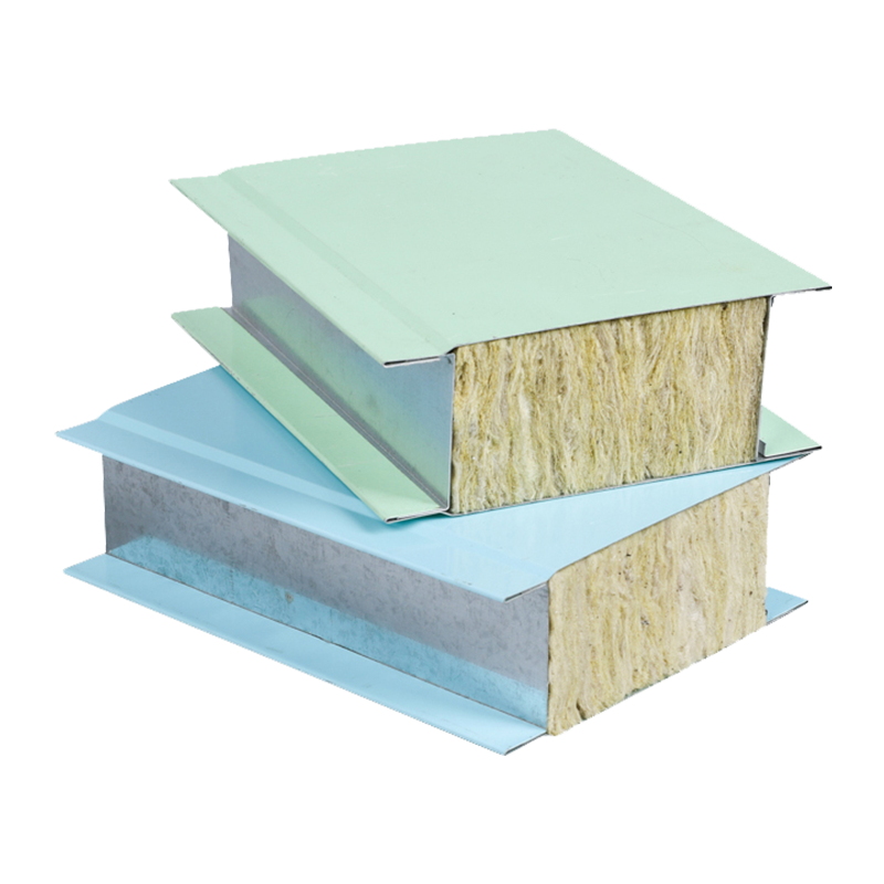 OEM/ODM FFU Replacement Filter for Cleanroom Fan Filter UnitsReplacement HEPA filter for fan filter units, available in H13–U17 grades and common sizes, with gel or gasket sealing options.View Product →
Two tolerances matter more than the efficiency rating. The seal comes first: an H14 filter in a poor frame leaks like an unsealed duct, which is why ISO 14644-3 requires a PAO or DOP scan of every installed filter at its final position. The second is the change-out point: filters are replaced at roughly twice their clean pressure drop, or about 450 to 500 Pa for a terminal HEPA, not on a fixed annual schedule.
Airflow Pattern: Unidirectional or Mixed
ISO 5 and cleaner requires piston flow: HEPA supply across the full ceiling, low returns on the wall opposite the critical zone, and nothing obstructing the path between them. Design velocity is 0.3 to 0.5 m/s measured 15 to 30 cm from the filter face, with roughly plus or minus 20 percent uniformity across the working area. A room averaging 0.45 m/s that drops to 0.2 m/s behind a machine bench is not unidirectional in any useful sense.
ISO 6 to 8 can use mixed flow with partial ceiling coverage and costs far less. Fan filter units suit that layout because each unit trims individually, and a 1,200 x 600 mm unit at 0.45 m/s moves about 1,000 to 1,300 m³/h while adding 150 to 250 W of fan heat. Twenty of them can add 3 to 5 kW that load calculations often credit to process equipment instead.
OEM/ODM Ceiling-Mounted Fan Filter Unit for Cleanroom Air SupplyCeiling-mounted FFU combining fan and high-efficiency filter, with modular use, speed control, and optional ULPA or centralized control.View Product →
Returns deserve equal attention. Low-level wall returns about 30 cm above the floor keep air sweeping the occupied space instead of short-circuiting across the ceiling.
Pressure Cascade, Temperature and Humidity
Pressure is what stops contaminants moving from a dirtier space into a cleaner one. Typical values:
- 10 to 15 Pa between adjacent spaces of different classes, with 5 Pa as the practical floor when doors are closed and the envelope is tight.
- Negative pressure of 10 to 30 Pa for hazardous or cytotoxic handling rooms, measured against the corridor rather than the outside air.
- Door interlocks, airlocks and interlocked pass-through windows to keep the cascade intact while materials move.
Temperature and humidity are easier to name than to hold. Pharmaceutical and medical device rooms commonly run 20 to 24 °C with a 1 to 2 K tolerance and 45% ± 5% RH; semiconductor and battery areas tighten both. There, humidity control protects hygroscopic powders, limits static discharge and keeps condensation off cold surfaces inside the envelope.
The Envelope Decides Whether Setpoints Hold
An HVAC system can only maintain a cascade if the room leaks less than the design assumes. Panel joints, door gaskets, cable penetrations and window frames are where pressure disappears; a wall leaking 5 percent of supply air can pull a 15 Pa cascade down to a few pascals and leave the control loop fighting itself.
Cleanroom Sandwich Panels and Modular Wall Panel SystemsCategory of cleanroom sandwich and modular wall panels, including machine-made and manual options, doors, windows, profiles, and airtight construction components.View Product →
That is why panel specification belongs in the HVAC conversation rather than a separate procurement folder. Insulated panels with continuous cores, gasketed double-seal doors and aluminium profiles with integrated seals give the mechanical designer a predictable leakage figure, while flush surfaces with minimal ledges leave fewer places for particles to settle.
Energy, Controls and Commissioning
Recirculation normally runs at 70 to 90 percent of supply air, with only makeup volume drawn from outside. That single early decision affects operating cost more than any filter upgrade, because outdoor air carries the full sensible and latent load.
Controls should be pressure-independent. VAV terminals or a modulating recirculation fan keep the room balanced as filters load; a fixed-speed fan delivers less air every month until particle counts drift. Night setback to 60 or 70 percent fan speed is usually acceptable where recovery time has been verified.
Commissioning proves the design: air volumes, filter integrity, room pressure, particle counts and recovery time after a simulated contamination event, with re-verification at intervals set by the applicable GMP or an internal quality system. If panel types and construction methods are still open, our cleanroom system selection guide covers the trade-offs that sit upstream of the HVAC design.
Frequently Asked Questions
How many air changes per hour does an ISO 7 cleanroom need?
Most ISO 7 rooms are designed between 25 and 60 ACH, and 30 to 40 ACH is common. The number should come from particle generation, internal heat load and required recovery time, not from a value copied between projects.
Can one air handling unit serve several cleanliness classes?
Yes, if each branch has a pressure-independent control device and the cascade still holds when every terminal adjusts. A single duct with manual dampers does not work, because filter loading changes the balance within months.
What is the minimum pressure difference between a cleanroom and its corridor?
Design for 10 to 15 Pa. Five pascals is the practical floor and leaves no margin for a door opening or a leaky penetration. Hazardous rooms run the same magnitude in the negative direction.
How is leak testing performed?
An aerosol challenge, PAO or DOP, is released upstream of the installed filter, and the downstream face and frame are scanned with a photometer following ISO 14644-3. Airflow direction is verified separately with smoke at doors and transfer openings.
Good cleanroom HVAC system design is mostly a sequencing discipline: class, cascade and load first; then air volume, filtration and distribution; then an envelope tight enough to make all of it repeatable. Projects go wrong when that order is reversed and the mechanical system becomes a patch on a fixed architectural layout.
If you are at the stage where the panels and the air handling strategy still need to agree with each other, send the room schedule and drawings to our engineering team and we will work through the cascade, filter coverage and envelope details with you.
Message Feedback
Product Categories
Easily navigate and discover our complete range of solutions through our logically structured product
categories.



- E-Mail: [email protected]
- Tel: +86 18968239620
- Address: Room No.905, He Yuan Mansion, No. 382, Tianda Lane, Ningbo Southern Business District, Yinzhou Ningbo China
Quick Links
Contact Us
© Copyright Zhejiang Kaisier Clean Technology Co.,Ltd.
All Rights Reserved.
 Cleanroom Systems Manufacturer
Modular Cleanroom Solutions Factory
-
+86 18968239620
-
-
